

Installation Center
Plan your WeVolt Apex install the right way.
A clear wiring diagram, a complete part list, and a fitment questionnaire that hands your truck details to our engineering team — all in one place.
How the eAPU Works
Interactive power flow for driving, parked cooling and starter-battery support.
Read moreTruck Compatibility
Check alternator headroom, battery type and mounting fitment before ordering.
Read moreCustomize Your Solution
Cable lengths, brackets and configuration options for your truck.
Read moreInstallation & Wiring Guide
Interactive diagram with every cable, fuse and busbar — plus the document package supplied with confirmed orders.
Read more01 · System Configuration & Wiring
See the whole system on one page.
Battery, DC-DC, HVAC, inverter and protection on a single wiring diagram. Match the labels in your cab to the labels below — no guessing where each cable runs.
VEHICLE EQUIPMENT
12V Vehicle System
Existing truck equipment
- Starter battery + alternator
- Charging source for the eAPU
CORE 02 / ENERGY STORAGE
Auxiliary LiFePO4 Battery
WeVolt WTTB-24V-314Ah / 25.6V 314Ah
- EV-Grade cells · 200A JK BMS
- 157A continuous / 200A max
- 24V nominal system class
CORE 01 / DC-DC CHARGER
Bi-Directional DC-DC Charger
WTDC-12-24V-50A
- Forward: 29.2V / 50A
- Reverse: 14.4V / 100A
- IP65 / ACC + RMT control
- Factory internal 150A fuse retained
CORE 03 / HVAC — INDOOR
HVAC Indoor Unit
WeVolt WTAC-24V-10C-5H / 24V DC
- 10K BTU cooling & 5.5K BTU PTC heating
- 100A factory heater protection
- Evaporator fan: 2–8A · PTC heater: 66.6A
CORE 03 / HVAC — OUTDOOR
HVAC Outdoor Unit (Compressor & Condenser)
WeVolt WTAC-24V-10C-5H / 24V DC
- 900W rated electrical input
- 38A rated / 10–45A operating
- 60A factory main protection
- 15A factory condenser-fan protection
CORE 04 / AC POWER
3kW Pure Sine Inverter
WeVolt IU24-3KW / US series
- 24V DC input → 3,000W output
- AC options: 100 / 110 / 115 / 120V · 50/60Hz
- DC input: 145A continuous / 154A max
- W0
1/0 AWG · 1m each
5/16" Tinned Cu Lug
Main positive battery lead
- W1
2 AWG · 1m each
5/16" Tinned Cu Lug
12V vehicle system → F1 fuse
- W2
4 AWG · 4m each
5/16" Tinned Cu Lug
DC-DC ↔ 24V bus (longest run)
- W3
2 AWG · 1m each
5/16" Tinned Cu Lug
Inverter ↔ 24V bus
- W4
16mm² · 5m each
Approx. 5 AWG / M10 lugs
HVAC indoor & outdoor feeds
- W5
8mm² · 3m each
Approx. 8 AWG / M8 lugs
Source protection branches
- F0
250A · Class T fuse
170V DC / 50kA — main battery protection
- F1
150A · Littelfuse MEGA
32V DC · 100A cont. / 105A max · fuse at vehicle battery positive
- F2
80A · Littelfuse MEGA
DC-DC output protection
- F3
200A · Class T fuse
170V DC / 50kA — inverter protection
- S0
350A · Main switch
Manual disconnect for service
- BUS
500A busbars
Battery positive distribution
- SRC
Source protection¹
Installer selected; 100A / 60A are factory fuse ratings, not source-fuse ratings
- G1
Chassis / protective bonding
Bonding details follow the vehicle and product manuals
While driving, the 12V truck charges the 24V house battery through the DC-DC charger. When parked, that battery runs the A/C and — if fitted — the inverter, and can support the starter battery when enabled. All loads share one 157A continuous / 200A max battery limit; plan simultaneous HVAC and AC appliance loads within it. Charger enable uses ACC / RMT signals — see the charger manual for pinout and protection.
See the interactive power-flow diagram- B1
Truck starter battery
Existing chassis battery bay
Truck starting system
- DC1
Bidirectional DC-DC
Chassis equipment space
12V / 24V two-way charging
- B2
WeVolt house battery
Chassis equipment space
Stores energy for cab loads
- H1
A/C indoor unit
Under the sleeper bunk
Delivers conditioned cab air
- C1
A/C outdoor unit
Outside, behind the sleeper
Rejects heat to outside air
- INV1
Inverter (optional)
Inside cab equipment area
Provides 120V appliance power
- —
Heater (optional)
Cab / under-bunk
Cab heat + engine preheat
Illustrative placement for a conventional sleeper truck. Tags match the wiring diagram above; the heater is not shown on it. Starter battery is existing truck equipment. Final mounting, clearances and heater routing depend on the truck model.
Check compatibility for your truck* Circuit currents follow the supplied configuration. Manage combined loads within the battery limit; transient surge currents are not shown.† F0 / F3 follow the specified fuse ratings. Exact fuse identification and cable / fuse protection coordination require confirmation.¹ HVAC source protection is installer selected. The 100A / 60A values in the unit cards are factory fuse ratings, not additional source-fuse ratings.System overview, not to scale. Main switch OFF does not isolate charger power. Follow the installation manuals and isolate all sources before service.
See the full bill of materials in the next section.
Open Part List02 · Standard System Part List
Every box, every cable, every fuse.
The complete list shipped with a standard WeVolt Apex 24V order. If your installation needs different lengths or extra protection, our engineering team can adjust.
01 · Core Components
Core product categories are separated from the installation accessory kit for easier receiving and inspection.
| Product | Description | Key Specification | Package | Unit |
|---|---|---|---|---|
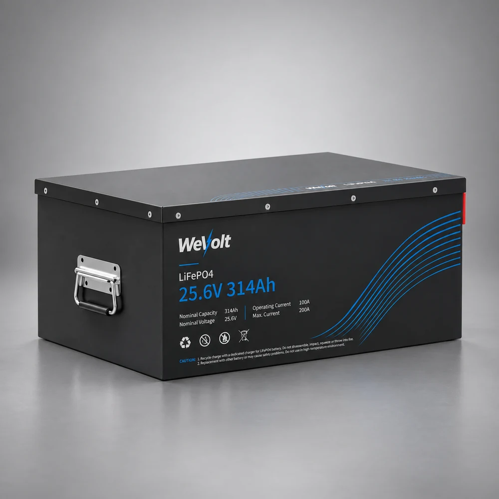 Row 1 | Auxiliary LiFePO4 Battery | 24 V / 314 Ah | Included | 1 |
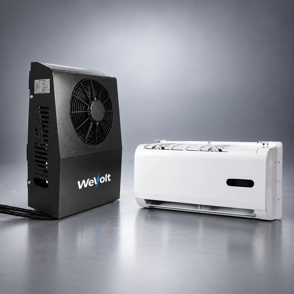 Row 2 | Variable-Speed A/C System | 10K BTU cooling 5.5K BTU heating | Included | 1 Set |
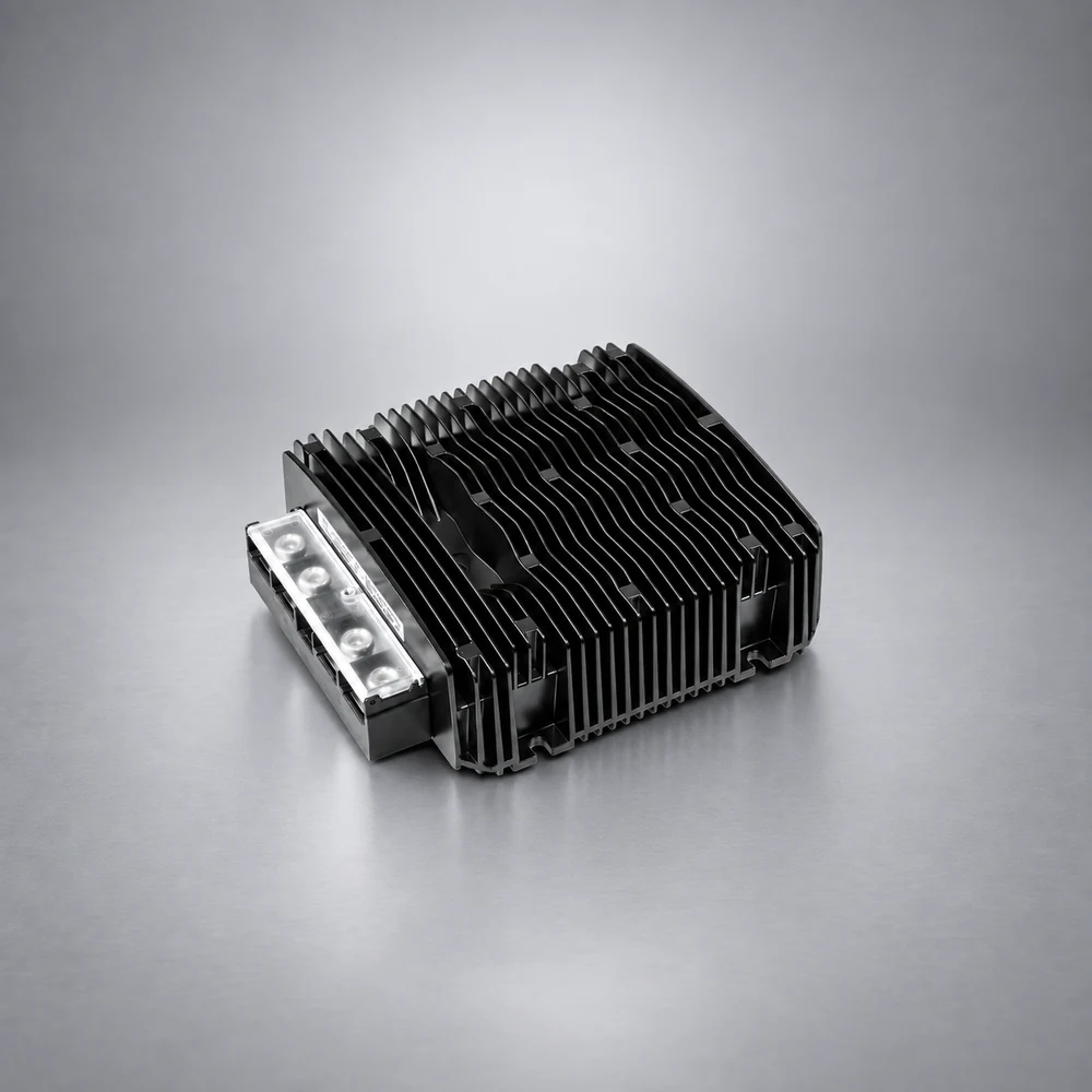 Row 3 | Bidirectional DC/DC Charger | Forward: 29.2 V / 50 A Reverse: 14.4 V / 100 A | Included | 1 |
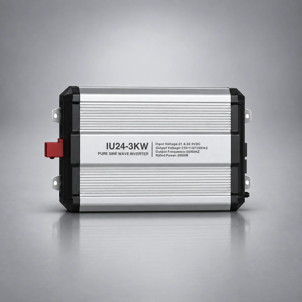 Row 4 | Pure Sine Wave Inverter | 24 V / 3,000 W | Optional | 1 |
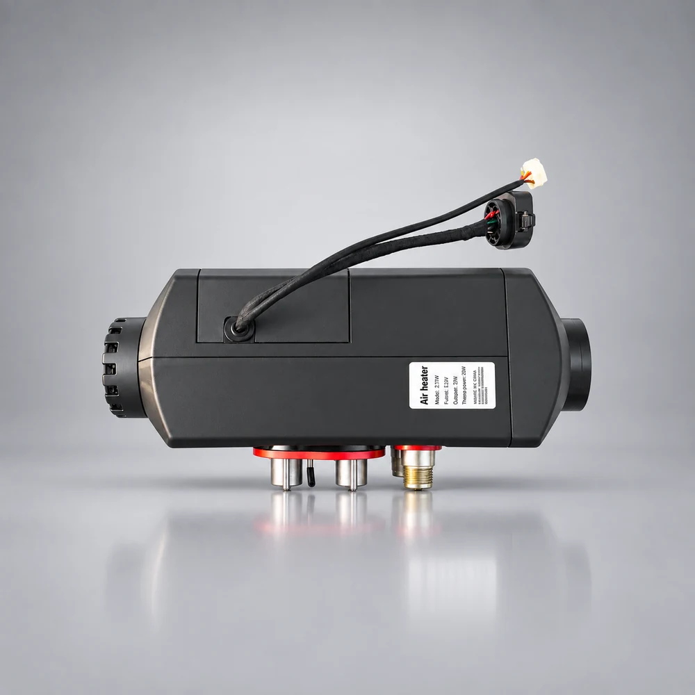 Row 5 | Diesel Engine Preheater & Cab Heater | 5,000 W | Optional | 1 |
Package Status: Items marked Included are part of the standard system configuration shown in this document. Optional items are supplied only when selected by the customer.
02 · Installation Accessories
Separate system-level installation accessory kit. Representative photos are shown for identification; quantities and specifications below follow the Official Part List.
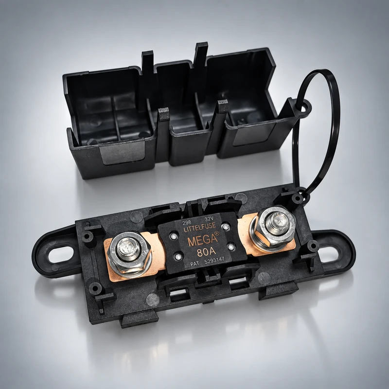
Fuse (with fuseholder)
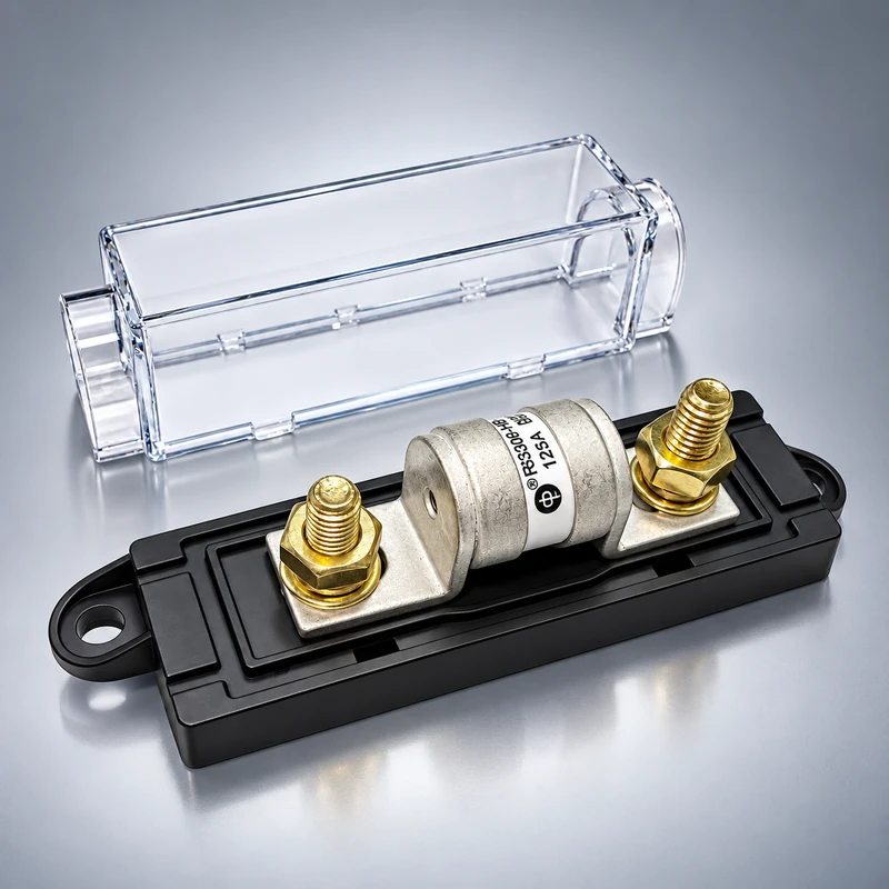
T Fuse (with fuseholder)

Busbar

Main switch

Lugs

Cables

Heat shrink

Loom

P-clamp

Zip tie
| Item | Specification / Size | Qty / Length | Class |
|---|---|---|---|
| CIRCUIT PROTECTION & SWITCHING | |||
| T Fuse (with fuse holder) | 170 V DC / 200 A | 1 | Accessories |
| T Fuse (with fuse holder) | 170 V DC / 250 A | 1 | Accessories |
| Fuse (with fuse holder) | 32 V DC / 80 A | 1 | Accessories |
| Fuse (with fuse holder) | 32 V DC / 150 A | 1 | Accessories |
| Main Switch | 350 A | 1 | Accessories |
| POWER DISTRIBUTION | |||
| Busbar | 500 A | 1 | Accessories |
| CABLE & TERMINATION | |||
| Lugs (UL) | M8, for 2 AWG | 16 | Accessories |
| Lugs (UL) | M8, for 4 AWG | 8 | Accessories |
| Lugs (UL) | M8, for 1/0 AWG | 10 | Accessories |
| Cables (UL) | 2 AWG | 2m each | Accessories |
| Cables (UL) | 4 AWG | 4m each | Accessories |
| Cables (UL) | 1/0 AWG | 1m each | Accessories |
| Heat Shrink (UL) | 13mm for 2–4 AWG | 5m | Accessories |
| Heat Shrink (UL) | 16mm for 1/0 AWG | 5m | Accessories |
| ROUTING & MOUNTING | |||
| Loom | PA 14mm | 20m | Accessories |
| Loom | PA 20mm | 10m | Accessories |
| P-Clamp | 24mm | 20 | Accessories |
| FASTENERS & GENERAL | |||
| Nuts | M5, 18mm | 100 | Accessories |
| Nuts | M6, 18mm | 50 | Accessories |
| Nuts | M8, 18mm | 40 | Accessories |
| Zip Tie | 8.8mm × 400mm | 100 | Accessories |
Important — Package Scope
This list covers system-level components and the separate eAPU installation accessory kit. Accessories already included inside an individual product package are not duplicated here. For example, cables supplied with the A/C unit are listed in the separate A/C manual / packing list.
Need a different length, extra protection, or a tailored quote?
Open Fitment Check03 · Compatibility & Parts List Request
eAPU Compatibility & Detailed Parts List Request Form
For truck fitment review, system configuration and purchase planning.
What happens next
- 01
Submit the form
Truck basics + duty cycle + your email.
- 02
Engineering review
Our team checks compatibility and sizing.
- 03
Tailored config
You receive a part list and a quote.
- 04
Quote & pilot
Review your parts list and quote — fleets get a 3–5 truck pilot proposal.
What you get back
A truck-specific parts list — component models, cable gauges, fuse ratings and quantities — plus a quote, within one business day.