
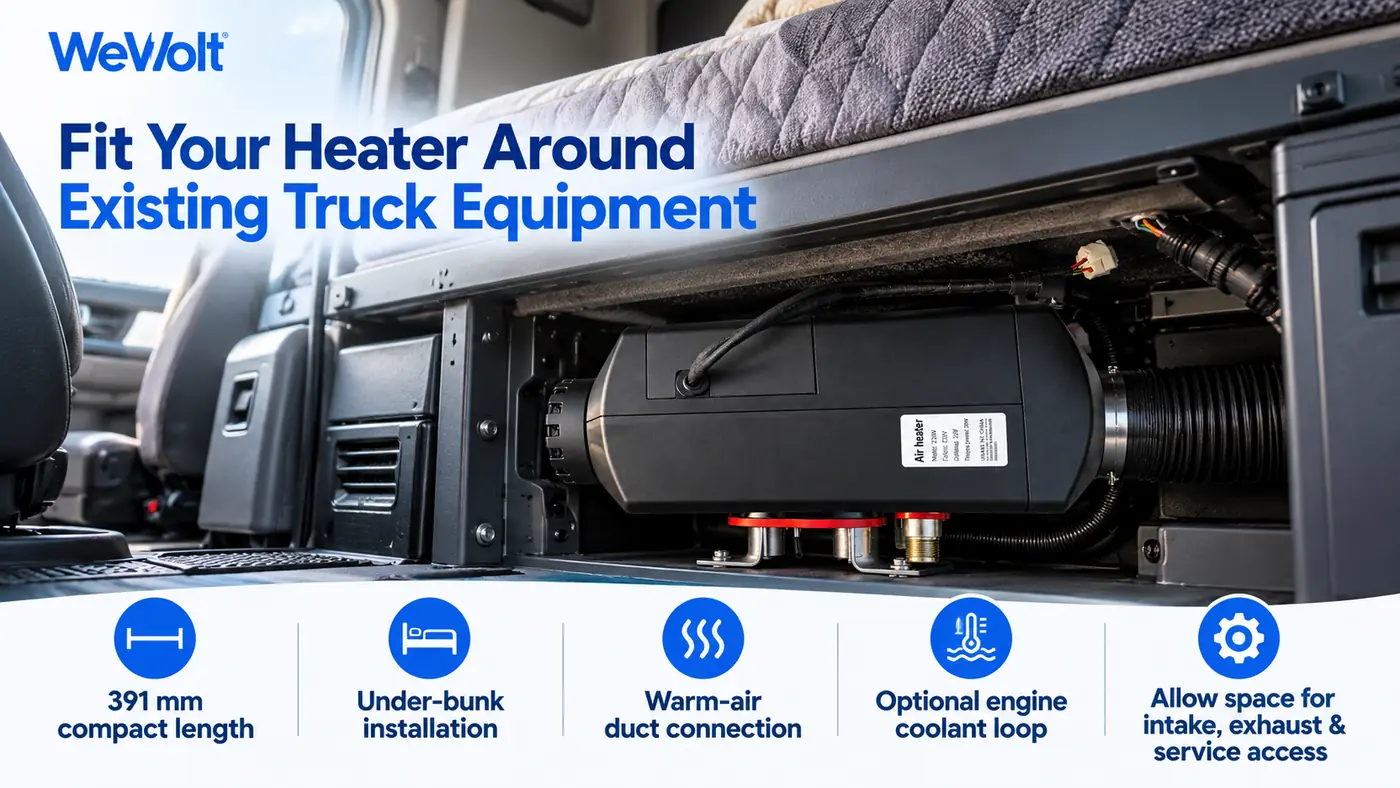
A diesel parking heater is a combustion heating device that runs independently of the main engine. A diesel heater installation on a semi-truck comprises four independent circuits — fuel supply; combustion air intake and exhaust; the low-voltage power supply; and, where the model provides it and engine preheating is required, a coolant circulation loop — with the layout of the warm air ducts determining how heat is delivered inside the sleeper compartment.
These four circuits are independent of one another and must be checked separately against the conditions of the vehicle; the absence of any one of them affects either function or safety. This article defines the installation object and the scope of the circuits, then works through the differences between three categories of units; the vehicle conditions to be verified before installation; mounting position and securing; combustion intake and exhaust; fuel take-off; the coolant circuit and engine preheating; power supply and protection; duct layout; first start-up and acceptance; and the position of the heater within the WeVolt Apex eAPU. It does not replace the installation manual supplied with the unit: pipe diameters, wire gauges, fuse ratings, tightening torques, exhaust clearances and labour times are those stated in the product manual for the selected model and in the vehicle's technical documentation.
1. Installation object: three categories of units and four circuits
Parking heaters divide into three categories by their heat transfer medium and function. Air heaters transfer the heat of combustion to air through a heat exchanger, and a blower delivers the warmed air into the sleeper compartment and cab; these units have no engine preheating function. Coolant heaters transfer heat to the engine coolant; beyond engine preheating and defrosting they can also supply heat to the compartment through the vehicle's original heater core. Dual-function heaters use one heat source to serve the air side and the coolant side together, with both circuits sharing the combustion chamber and heat exchanger.
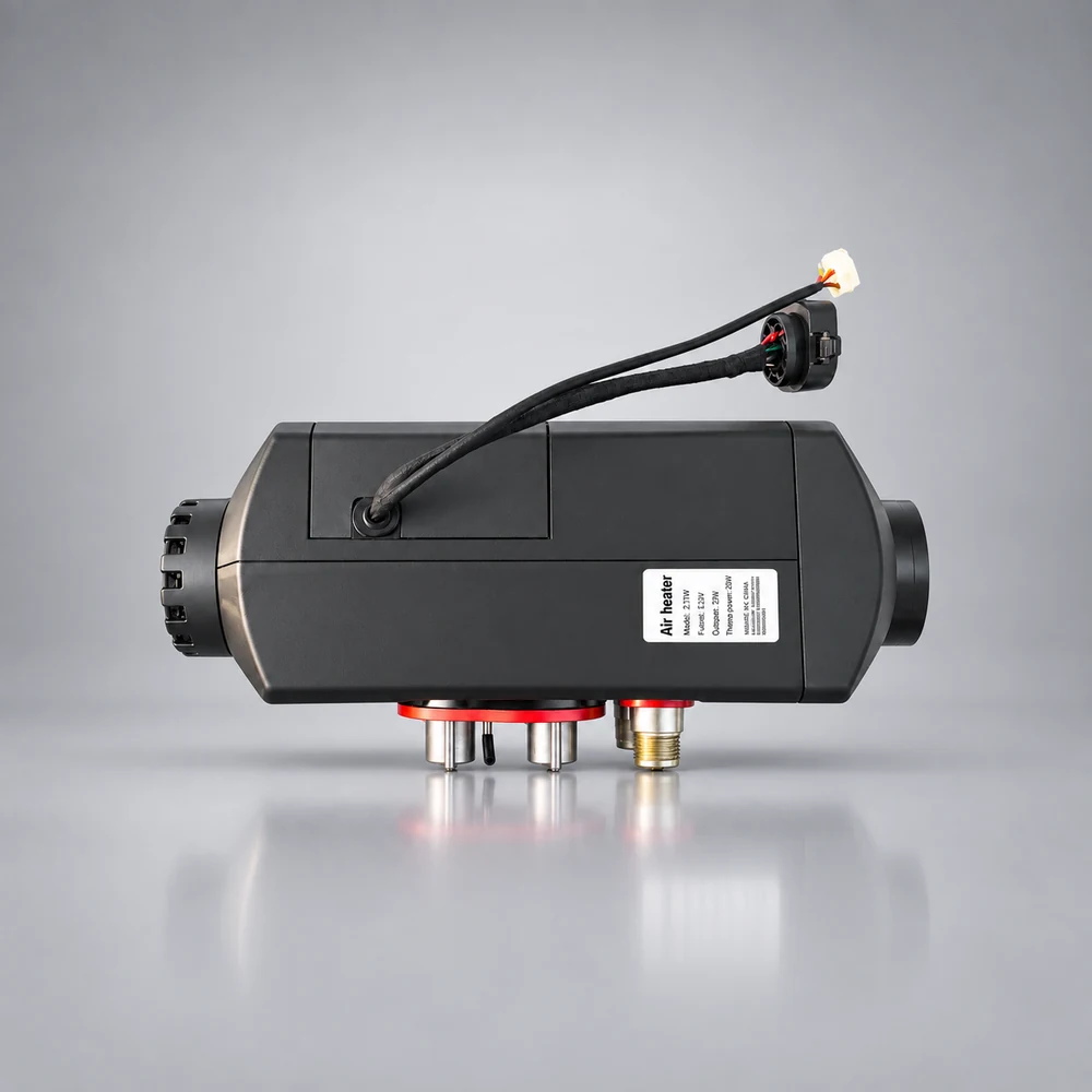
The diesel heater supplied with the WeVolt Apex eAPU belongs to the dual-function category, and the rated values in the official component manual for this 5kW diesel heater are set out below. Because the air side and the coolant side share one main unit, a coolant heater installation and a bunk heater installation are carried out as a single job rather than as two separate fitments.
The 5kW figure is the rating of the entire unit; it is not the output of the air side alone, and it should not be compared multiplicatively with the roughly 5,500 BTU/h of cabin heating a parking air conditioner provides. The two are measured in different units and deliver heat to different objects, and the distribution ratio between the two sides of a dual-function model has not been disclosed. The rated output reflects the unit's order of magnitude and design conditions, not a temperature-rise rate or a maximum temperature in a specific vehicle.
Correspondence between the four circuits and unit functions
Fuel supply, combustion intake and exhaust, and the low-voltage supply are common to all three categories; the coolant circulation loop is installed only where engine preheating is required and the selected model provides a coolant side — a distinction often overlooked in general guidance on how to install a diesel heater.
A dual-function model is not two separate units bolted together; it distributes heat from a single combustion source to both sides. The warm air ducts and the coolant lines are installed separately, but they share one mounting location for the main unit and the same fuel lines, intake and exhaust pipes, and supply circuit. Keeping the two functions distinct is what tells you which circuits a given truck actually needs.
A truck that requires sleeper heating alone does not include a coolant circulation loop in its installation. Where cold-start preparation for the engine is required, the coolant connection point, circulation pump and bleeding conditions must be checked: a correctly installed coolant loop is a precondition of the preheating function, not a universal step in every diesel heater install.
The same category name may cover different constructions in different manufacturers' catalogues. The specification sheet and the manual supplied with the unit identify the circuits more reliably than the category name, so check the connection list for the specific model before fixing the scope of work.
2. Vehicle conditions and documentation to verify before installation
Installation conditions are determined by the vehicle. Tank construction, the low-voltage electrical architecture, the layout of the cooling circuit and the space beneath the sleeper differ by truck model, model year and original equipment, so six groups of conditions should be checked before a semi truck diesel heater installation is scoped and the parts list is finalised.
Versions of the same product category with different rated voltages coexist on the market, and heavy-duty trucks themselves use different low-voltage architectures. Verify the rated supply voltage, the vehicle's low-voltage system, the power take-off point, wire gauge and fuse configuration against the selected model, and confirm the connection details from the product manual. The voltage value itself is not a measure of quality; compatibility with the vehicle's electrical system is the only criterion.
Before work begins, confirm that the installation manual, wiring diagram and parts list supplied with the unit are complete; where anything is missing, obtain it from the supplier first. The official parts list also draws a separate boundary for accessories: the cables, fuses and distribution components in the system-level accessory kit do not cover the fuel, intake and exhaust, coolant and low-voltage harness parts supplied with the heater itself, and the two lists must be checked separately.
No commitment is made here that any truck model can be fitted directly, and no fixed labour time is given. Installation depends on the truck layout and electrical conditions, and the actual time varies with the interfaces provided by the manufacturer, the selected model and the working environment.
Checking conditions is preparatory work, not a construction step. The execution of fuel lines, the coolant loop and low-voltage protection follows the vehicle service documentation and the manual supplied with the unit; pipe diameters, wire gauges, fuse ratings, tightening torques, exhaust clearances and fuel pick-up depths vary with the model and the vehicle.
3. Mounting position, securing and service access
Once the position of the main unit is fixed, the routing of the fuel line, intake and exhaust pipes, coolant hoses and warm air ducts is largely determined. The position must satisfy four requirements at once: safe clearances, fixing strength, a workable pipe route and access for service.
Trucks live in continuous vibration, so the unit bracket, pipe supports and harness fixings must all be arranged for that environment. Where the main unit, pipes and harness share an area, keep separation and fixing distances so that rigid pipes do not rest on sharp edges and the harness stays clear of hot components. Loom tubing and P-clamps only organise and support the run, and their sizes must match the pipes and harness selected.
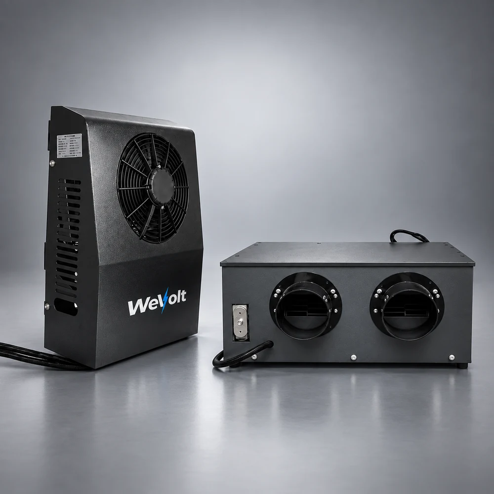
The indoor and outdoor units of a split parking air conditioner, the house battery and the heater main unit are separate pieces of equipment, and their positions should be planned together. Storage space under the sleeper being taken up, outlets blocked and the return air path obstructed are the space problems most often reported after a bunk heater installation, so equipment, storage and the driver's living area should be settled at the positioning stage — particularly where a heater for truck sleeper use is being added to an existing system.
Bracket forms, fixing methods and the location of any openings vary with the truck model and are determined from the vehicle structural documentation and the manual supplied with the unit. Opening dimensions, bracket specifications and tightening torques are not given here.
4. Combustion air intake and exhaust
Combustion equipment has two air paths of different kinds. Combustion air is drawn from outside the vehicle into the sealed combustion chamber, and the gases leave through the exhaust pipe; warm cabin air, by contrast, is heated through the heat exchanger and blown into the sleeper, taken from the cabin and returned to it. The two paths must not be connected to each other, and the combustion exhaust must never be led into the warm air ducts. The intake and exhaust ports listed in the official component manual refer to the first of these paths.
The location of the exhaust outlet should account for stationary and low-speed operation, open windows, adjacent parked vehicles and changes in wind direction. Exhaust gas collecting beneath the vehicle and entering the sleeper through a door, window or the fresh-air inlet is the situation to guard against in enclosed or partly enclosed conditions. A carbon monoxide alarm provided in accordance with local safety regulations forms part of the conditions of use for combustion equipment, and an incorrectly routed diesel heater exhaust is the most common cause of such problems.
Three safety requirements apply to the installation and use of any combustion heater:
- The exhaust must be led outside the vehicle. Combustion gases must not be discharged inside the cab, beneath the sleeper or in a closed garage, and combustion heaters must not be operated in enclosed spaces.
- The two air paths must not be joined. Combustion air and combustion exhaust never share ducting with the warm cabin air.
- Protective devices follow local regulations. The selection, location and verification of a carbon monoxide alarm follow local safety regulations and the instructions supplied with the unit.
These conditions are installation and operating requirements, not a commitment of zero fire or carbon monoxide risk. The sealing and securing of the exhaust, intake and warm air ducts should be rechecked at first start-up and during subsequent maintenance.
5. Fuel supply and fuel take-off
The heater draws a small quantity of diesel from the vehicle tank and delivers it through filtration and a metering pump into the combustion chamber. The fuel circuit consists of the take-off point, the fuel line, the filter, the pump and the connections, and the quality of its installation determines whether fuelling is continuous and free of leaks.
The verifiable consumption range is roughly 0.15–0.52 L/h of diesel, with a fuel pump rated at about 18 W. Consumption varies with the output setting and the ambient heat load; the glow plug and blower draw more power during start-up than in steady operation. A diesel heater fuel line therefore carries a small but continuous flow — the unit consumes diesel and a little electricity, and does not provide heat at no running cost.
Limits on fuel-system work: the take-off method must be confirmed from the tank construction and the manual supplied with the unit. Drilling into the tank at an arbitrary location is not appropriate, and the vehicle's high-pressure fuel lines should not be altered; work involving tank penetrations, changes to fuel lines and the sealing of the fuel system belongs with suitably qualified personnel following the vehicle manufacturer's documentation.
Engine coolant preheating acts on the engine cooling circuit. It does not change the low-temperature properties of the fuel in the lines and is not a substitute for measures against diesel waxing or gelling; fuel supply in extreme cold must be judged from fuel quality, the vehicle's fuel system and the actual ambient temperature.
6. Coolant circuit and engine preheating
The coolant loop is installed on one class of vehicle only: where the selected model has a coolant side and the truck requires engine preheating or defrosting. An air-only heater involves no such loop. The loop transfers combustion heat through the heat exchanger into the engine coolant, with a circulation pump moving coolant between the main unit and the engine so that coolant temperature can be raised while the main engine is shut down.
Hose routing must also allow for vibration while driving, clearance from hot exhaust components and the natural circulation of coolant after shutdown. Where a non-return valve or other control component is required, its presence and orientation follow the manual supplied with the unit and the vehicle technical documentation.
The effect of preheating depends on a correctly installed coolant circulation loop, and on the engine model, coolant volume, pipe layout, ambient temperature and altitude. No preheating time or target temperature is given here; heating powers and temperature-rise times published for other systems vary considerably and cannot be transferred to a specific model. An engine preheater of this type is specified by its installation conditions, not by a guaranteed warm-up figure.
Functional boundary: engine coolant preheating serves cold-start preparation and defrosting. It is not fuel-line heating, wax prevention or anti-gelling, nor an emergency jump start or a substitute for the starter battery. Whether a coolant heater installation is carried out depends on whether the truck needs preheating, not on the rated output of the heater.
No commitment is made that any engine will reach a given temperature within a stated time, and no preheating performance is claimed for arbitrary extreme-cold temperatures or altitudes. Rated low-temperature conditions and high-altitude derating rules must be confirmed from the specification sheet of the selected model and the installation as built.
7. Power supply, fuse protection and grounding
A diesel heater makes its heat by combustion, but its electrical parts still need power: the controller, glow plug, metering fuel pump, blower and, where preheating is enabled, the circulation pump. These are supplied from the vehicle's low-voltage system, independently of the power loop formed by the 24V house battery, the parking air conditioner, the DC-DC charger and the inverter — the heater does not draw on the 8.04kWh stored in that battery.
Distinguishing the three circuits
Several electrical figures appearing in the system documentation belong to different circuits, and confusing them is a common error in diesel heater wiring. The supply objects and protective devices of the three circuits are set out below.
The electric heating current of about 66.6A and the corresponding 100A factory protection rating on the system configuration diagram belong to the PTC auxiliary heating branch of the parking air conditioner on the 24V side; they are not the current or the fuse rating of the diesel heater. The same document notes that source protection on the air conditioner side is selected by the installer, and that the factory fuse ratings on the unit cards are not additional source-fuse ratings. Transferring either figure to the sizing of the heater harness or its fuse would leave the protection mismatched to the load.
Four electrical checks
The installation accessory kit in the official parts list is a system-level kit, and the list states explicitly that accessories supplied with individual products are not repeated in it. The cable sizes, fuses, main switch and busbar ratings in that kit serve the 24V power loop — this is why the 250A fuse and 2 AWG cable in the kit are not heater components — while the harness, fuses and connectors supplied with the heater follow the manual and packing list for that model, sized from the actual cable length and current of the installation.
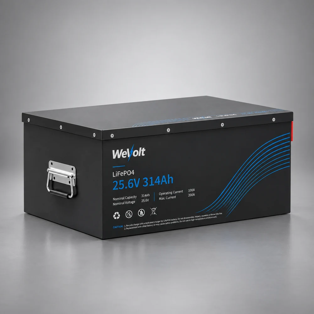
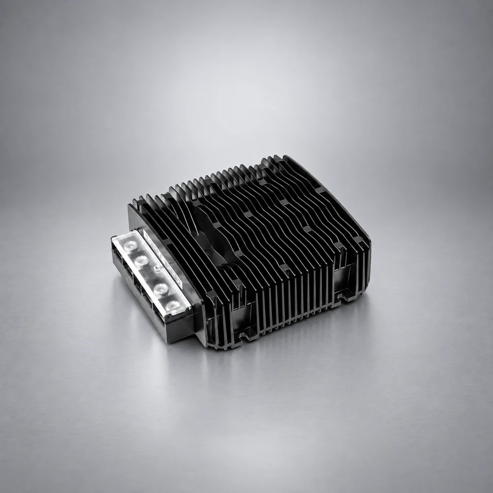
System boundary: the heater supply circuit is independent of the 24V house battery loop, so adding a diesel heater neither increases stored energy nor directly consumes the energy used by the parking air conditioner and onboard appliances. The house battery is a 25.6V / 314Ah LiFePO₄ unit storing 8.04kWh; the bidirectional DC-DC charger delivers up to 50A forward and 100A reverse, adjusting automatically to battery voltage, both figures upper limits.
Fuse amperage, cable gauge, terminal specifications and connection torques for the heater are not given here. Selection, crimping and protection of the low-voltage circuit must be calculated from the supplied wiring diagram, the installed cable length and the actual current; changes to the vehicle electrical system should be carried out by qualified personnel following the vehicle manufacturer's documentation.
Sizing the 24V power loop: wire gauge and fuse tables for the battery, charger and inverter8. Duct layout and sleeper air delivery
The warm air duct is the final section of the air side and determines how heat reaches the sleeper. Its layout is unrelated to the combustion air paths, but it bears directly on comfort: concentrated airflow, an obstructed return path, excessive duct length or too many bends all produce local overheating while the far end stays cold — the issues most often raised in discussions of diesel bunk heaters in sleeper cabs.
A split parking air conditioner and a diesel heater are separate devices with their own air delivery paths. They can be arranged independently, but outlet positions, the return air area and the space each occupies must be coordinated within the same compartment so that the airflow from one is not blocked by the structure of the other; the air conditioner's supply and return requirements continue to follow that model's installation manual.
Duct diameters, outlet dimensions and permissible duct lengths vary with the model and the vehicle layout, and no single set of values is given here. The ducts, storage arrangement and bracket forms must be designed for the vehicle; adding a heater does not by itself resolve uneven temperature distribution in the sleeper, nor does it remove the layout requirements on the air conditioner side. A truck cab heater, a sleeper heater and a semi truck heater are often names for the same category, but their ducting is always specific to the installation.
Duct layout is part of the installed result, not a rated value of the equipment. The rise in cab temperature depends on insulation, outside temperature, airflow volume and other loads running at the same time, and cannot be calculated directly from the rated heating output.
9. First start-up, acceptance and common installation deviations
Once the four circuits are installed, the checks before energising and the first start-up establish whether the installation is sound. Acceptance follows the circuits in order and has no fixed duration; initial priming of the fuel line and bleeding of the coolant loop may require several cycles before operation stabilises.
Checks before energising
The main unit and bracket are secure; the fuel, intake, exhaust and coolant connections are correctly made and free of leaks; supply polarity, grounding, fuses and harness fixings follow the supplied wiring diagram; the warm air ducts are unobstructed with neither the outlets nor the return opening blocked. Work requiring isolation of the supply is carried out only after all sources have been isolated in accordance with the instructions.
First ignition and observation during operation
The controller follows a fixed sequence — the glow plug and fuel pump are energised, the blower starts, the combustion chamber ignites, heat is delivered through the heat exchanger, the output falls to a holding level once the set temperature is reached, and a purge cycle follows shutdown. During the first run, observe whether ignition succeeds, whether combustion sound is continuous, whether exhaust gases leave the vehicle properly, whether warm air reaches every outlet and whether any fault code appears. Start-up draws more power than steady operation, and repeated ignition attempts are common where fuelling is not yet continuous or air remains in a circuit. This sequence is the practical answer to how do diesel heaters work once the unit is fitted.
Checks during operation and after shutdown
During operation, check for fuel and coolant leaks, secure fixing of the exhaust pipe and silencer, an exhaust outlet clear of doors, windows and air inlets, correct functioning of the cab carbon monoxide alarm and even delivery at each outlet. After shutdown, recheck the connections, fluid level and fixings, and record the controller status in accordance with the supplied manual. A quiet diesel heater is not something that can be specified by a single figure, since perceived noise depends on the mounting position, fixing method, duct layout and cab insulation.
These deviations are common observations after installation, not failure-rate statistics, and they do not point to particular brands. Carbon deposits, restricted fuelling and blocked intake or exhaust appear as routine checks in industry troubleshooting material, where the usual order is to verify the supply and protective devices first, then the intake, exhaust and fuel filter, and then to read the controller status.
Who carries out the work should be decided from the available skills, tooling and warranty terms. The boundary between self-installation and installation by a service provider, and the checks an owner may perform, follow the supplied warranty statement and the supplier's support path; no conclusion is drawn here for individual cases.
Three boundaries apply to the acceptance stage:
- Conditions of use follow the supplied instructions. Whether anyone may remain in the sleeper during operation, and whether a carbon monoxide alarm is required, follow the manufacturer's instructions and local safety regulations; no recommendation is given here about overnight use during sleep, and such use is not described as a product function.
- No commitment of zero faults or zero fires is made. The outcome of troubleshooting depends on the condition of the vehicle and the quality of the work; demand-side discussion is not evidence of failure rates.
- No commitment of direct fitment to any truck model or of fixed labour times is made. The duration of the test run, the number of cycles and the acceptance items follow the supplied manual and the vehicle technical documentation.
10. System position within the WeVolt Apex eAPU and next steps
The WeVolt Apex eAPU is offered in four systems that share three basic components: a truck air conditioner, a 24V house battery and a DC-DC charger. The differences lie in whether 120V appliance power is added through the 3,000W pure sine wave inverter, and whether diesel heating and engine preheating are added through the 5kW dual-function diesel heater. The full designations are WeVolt Apex Essential eAPU, Apex Power eAPU, Apex Heat eAPU and Apex Complete eAPU.
The 5kW dual-function diesel heater is supplied with the Apex Heat and Apex Complete systems. Winter heating in the other systems depends on whether the selected air conditioner model has auxiliary electric heating, which means neither that those systems have no heating capability, nor that all four include a diesel heater as standard. The four systems are chosen by functional match rather than as a price ladder: Apex Power where appliance power is needed, Apex Heat where winter heating and engine preheating are needed, Apex Complete where both requirements are present.
Installation scope and system boundaries
The operating principle of a truck diesel heater and the reasons drivers add one, and the differences between diesel and electric heating in energy source and runtime effect, are covered in the companion articles below; the method for sizing the system-level 24V cables and fuses is given in the wiring guide. For any specific truck, the interface conditions of the four circuits, the scope of supplied accessories and the construction requirements still follow the vehicle service documentation, the manual supplied with the unit and the configuration list confirmed by the supplier.
Truck diesel parking heater: what the device is and how the combustion cycle worksDiesel heater vs electric heating: capacity on the same basis, battery runtime and cold-weather limitsFor system configuration, accessory scope, vehicle compatibility checks and product enquiries, contact [email protected].
Adding a diesel heater does not change the 8.04kWh capacity of the house battery and does not replace the cooling or electric heating functions of the air conditioner. The choice of system rests on the combination of heating and power functions required; specific installation conditions and accessory scope follow the official documentation and the vehicle service information.
References
Product specifications, system configurations and connection conditions are taken from the official WeVolt component manual, official parts list, system overview, system configuration diagram and air conditioner service manual. The external sources below concern equipment classification, idle reduction, low-temperature cold starting, supply conditions, installation elements and safety in use, and are publicly accessible. Manufacturer installation manuals and industry guides serve only as general references for circuit classification and the order of acceptance checks; their specifications, numerical values and construction steps do not apply to a specific model.
- 1U.S. Department of Energy, Alternative Fuels Data Center: Heavy-Duty Truck Idle Reduction Technologies. Lists auxiliary power units, cab or bunk heaters and coolant heaters among idle-reduction technologies, and notes that their economics depend on the amount of idling to be displaced. afdc.energy.gov
- 2U.S. Department of Energy, Alternative Fuels Data Center: Medium-Duty Vehicle Idle Reduction Strategies. Defines air heaters and coolant heaters and describes their operation, including heat delivered through the cooling circuit and heater core. afdc.energy.gov
- 3U.S. Department of Energy, Alternative Fuels Data Center: Idle Reduction Basics. An introduction to idle reduction with an entry point to the savings calculator, including the preconditions for the fuel-saving calculation. afdc.energy.gov
- 4U.S. Department of Energy: Idle Reduction. Covers idle-reduction research, the IdleBase regulatory database and compilations of anti-idling regulations at various levels of government. energy.gov
- 5U.S. Environmental Protection Agency: SmartWay. Maintains a list of verified idle-reduction technologies, with the equipment categories that have been confirmed. epa.gov
- 6DieselNet: Emission Standards. An entry point to road-vehicle emissions and idling-related regulations by country. dieselnet.com
- 7TRID, Transportation Research International Documentation (Transportation Research Board): Design and Optimization of Diesel Engine Cold Start Heating System under Extreme Cold Conditions, SAE Technical Paper 2026-99-0809. Uses a fuel-fired heater to heat coolant as a preheating approach, with the effect varying by heating power, flow rate and circuit layout. trid.trb.org
- 8SAE International: entry for the same technical paper, concerning low-temperature cold starting and low-temperature battery performance. sae.org
- 9SAE International: J300 Engine Oil Viscosity Classification. Classification by low-temperature viscosity and pumpability, relating to the increase in starting resistance at low temperatures. sae.org
- 10Webasto Group: Heating Solutions. The manufacturer's heating product lines, with the classification of air heaters and coolant heaters. webasto-group.com
- 11Eberspächer (Espar): official product entry, covering both air heating and coolant heating product groups. eberspaecher.com
- 12Heatso: All You Need to Know About Truck Parking Heaters. Synonymous designations for bunk heaters, selection differences between air and coolant heaters, and four checks covering heating power, fuel, voltage and installation. heatso.com
- 13Lincool: Cold Starts or Cabin Comfort — Where Diesel Parking Heaters Matter. Comparison of the two heating paths, fuel consumption examples by output setting, the dependence of supply voltage on the vehicle electrical system, and steady-state and start-up electrical consumption. lkcool.net
- 14ShiftOwt: Keeping warm in the HGV cab on a winter night out. Four installation elements from a driver's perspective — fuel take-off, exhaust, intake and low-voltage supply — and carbon monoxide safety guidance for combustion equipment. shiftowt.com
- 15Hello Portable: Freightliner Cascadia Bunk Heater Not Working — Quick Fix Guide. Controller ignition sequence, low voltage, blocked intake and exhaust, carbon deposits and other common check items, with the order of diagnosis. helloportable.com
- 16UNECE UN Regulation No. 122: uniform provisions concerning the type approval of vehicles with regard to combustion heaters and their installation. The regulation can be retrieved by its regulation number.
- 17Official WeVolt component manual, official parts list, system overview and system configuration diagram: heater ratings, the connection list, the scope of the system-level installation accessory kit, and the factory protection ratings of the PTC auxiliary heating branch of the air conditioner. Accessories supplied with individual products are not repeated in the system-level list.
Rated conditions, wiring and requirements for use are those stated in the product manual and the manufacturer's consistent instructions. The specification ranges listed here carry their conditions of applicability with them; specific installation values are taken from the manual supplied with the unit and the vehicle's technical documentation.