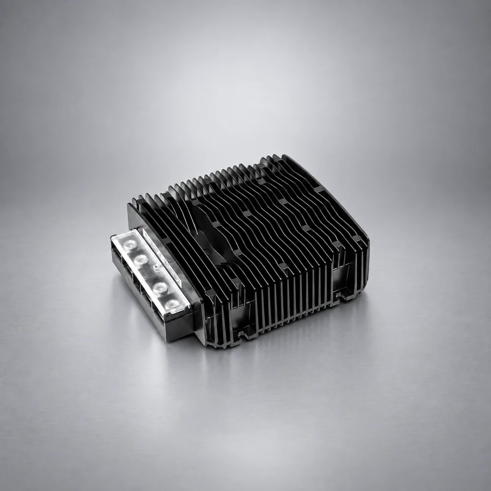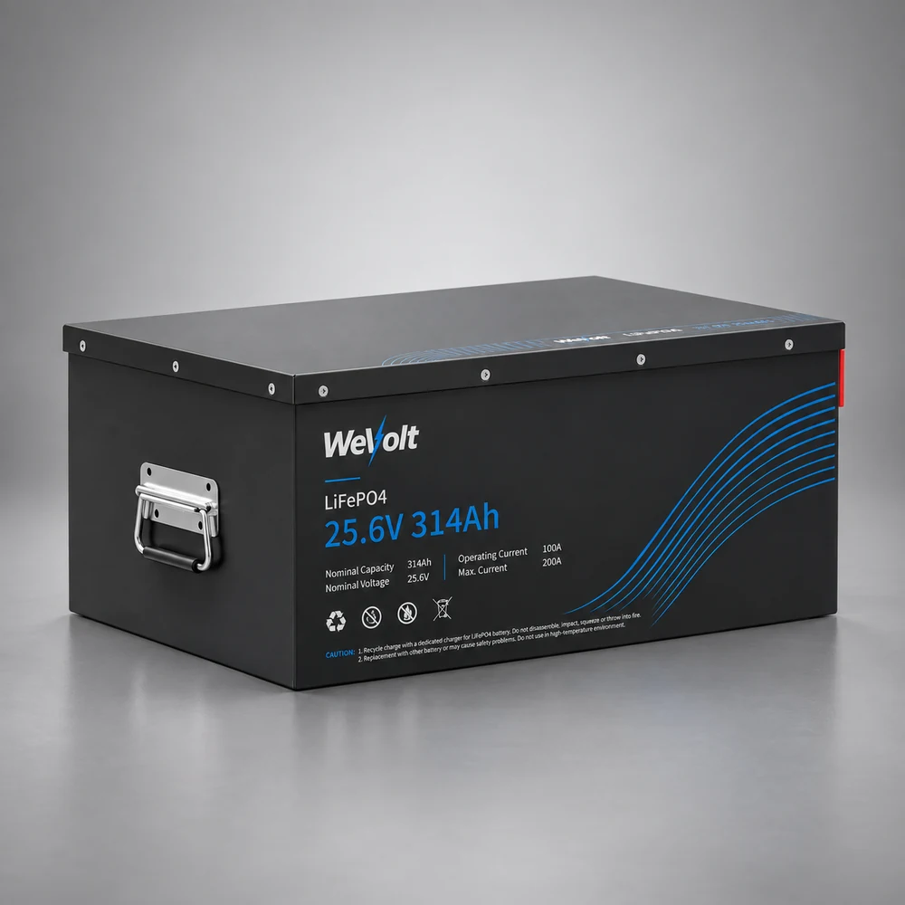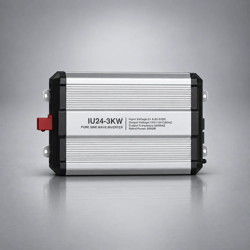

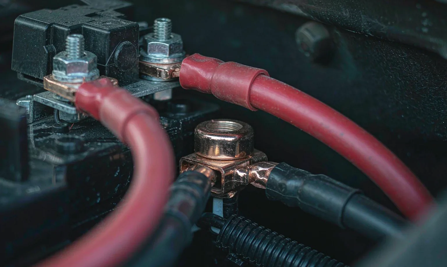
When truck owners search for fuse sizes, a fuse size calculator, an inverter fuse, or the right wire size for 3000w inverter installs, they are really asking one question: for this 24V system, how do I choose the wire and configure the fuses safely? Wire gauge and fusing are not boxes to fill in on an accessories list—they are the first safety gate of an eAPU installation. Undersized cable causes voltage drop, heat, and nuisance tripping; missing or misplaced fuses let an unprotected cable arc and catch fire during a short. This article uses WeVolt's published wiring specifications, the official WeVolt Apex eAPU parts list, and the System Technical Overview to explain both how to size things and why the specifications are what they are, with the boundaries stated. The example unit is the WeVolt Apex eAPU, designed and manufactured by WeVolt.
Why Wire Gauge & Fuses Are the First Safety Gate in an eAPU Installation
An eAPU is a high-current, low-voltage system: nominally 24V, with the battery circuit peaking at 200A. At low voltage, the same 1-volt drop is 4.2% of a 24V system but only 0.8% of a 120V household circuit—which is why run length and wire gauge matter far more for an eAPU than for household wiring. Undersized cable wastes voltage, generates heat, and trips protection repeatedly; a missing or incorrectly rated fuse lets an unprotected cable arc and start a fire during a short.
Many buyers searching fuse sizes or a fuse size calculator are not looking for a single "standard answer"—they want a method they can apply themselves. The WeVolt Apex eAPU ships with a complete installation accessories kit—Class T fuses, a main switch, busbars, and UL terminals and cables (what's in the box is answered in eAPU Installation, Warranty & Support). This article completes the picture: why these parts carry these ratings, and what to look at when estimating for yourself.
This article covers technical principles plus WeVolt's first-party specifications, positioned as the groundwork for installation planning. For self-install versus factory install, see DIY eAPU vs Factory Installation; for the bidirectional DC-DC wiring walkthrough, see Bidirectional DC-DC Charging.
WeVolt Apex eAPU Wire Gauge & Fuse Specifications (First-Party Evidence)
The table below is derived from first-party sources that corroborate one another: the Bidirectional DC-DC Quick Start Guide, the official WeVolt Apex eAPU parts list, the System Technical Overview, and WeVolt's official system configuration & power-flow diagram (shown below). These are WeVolt Apex eAPU's actual test and delivery specifications, not general recommendations—general principles are discussed in the following two sections.
WeVolt Apex eAPU official system configuration and power-flow diagram: 12V vehicle system, bidirectional DC-DC, 8.04kWh auxiliary battery, HVAC indoor and outdoor units, 3kW inverter, with W0–W5 cable runs and F0–F3 fuses
WeVolt Apex eAPU official system configuration & power-flow diagram — component ratings, the W0–W5 cable runs, and the F0–F3 fuse locations in one view.
One deliberate margin is worth pointing out before the numbers: where the DC-DC manual's hard requirement is 4 AWG (Side A) and 6 AWG (Side B), the kit ships 2 AWG and 4 AWG—one gauge thicker than the manual requires. The shipped values are what appear in the table and in the diagram above.
Wire gauge
Fuses and switching
These values come from the System Technical Overview; its footnote states that fuse/cable coordination is subject to confirmation, so the final matching follows the customer's released version. This article does not pretend the coordination is finalized (see Section 5 and the notes at the end).
How to Size Wire: Current × Length × Voltage Drop (method per Renogy)
The general selection steps below follow Renogy's Wire and Fuse Sizing Guide—Renogy is a mainstream reference for RV / off-grid low-voltage DC wiring, and its method transfers directly to the truck 24V scenario. Note: this is the general method; WeVolt Apex eAPU's first-party shipped values are in the table in Section 2—keep the two separate. Three general principles:
- Cable must be UL-listed stranded copper, rated above 105°C (221°F): higher temperature rating means higher ampacity and better safety; in the engine bay use tinned copper for corrosion resistance, and avoid aluminum (not worth the risk on low-voltage DC).
- Cable length = the combined positive + negative run: in a DC loop, current leaves through the positive and returns through the negative, so the effective conductor length is roughly 2 × the physical distance, and both legs must meet the gauge.
- The fuse rating must be below the cable's maximum ampacity (fuse < cable ampacity): under overcurrent the fuse opens first and the cable never overheats—this is the hard rule behind "the fuse protects the cable" (see Section 4).
Battery-circuit cable: look up by fuse rating, voltage drop < 8%
Renogy's battery-cable table assumes a voltage drop of less than 8% and is read by fuse rating and combined positive+negative length. A few representative rows (full table in Renogy's guide):
How to read it: first set the circuit fuse rating (Section 4), then check the actual combined length and take the matching gauge; the longer the run, the heavier the cable—when in doubt, go one size above the manufacturer's specification.
Solar cables (not this system's main loop) follow Renogy at ≤3% voltage drop and ambient ≤40°C (104°F); above 40°C, derate per NEC 310.15(B) (90°C insulation at 40°C ambient uses a 0.91 correction factor, roughly 9% derating), and derate another 15–25% when multiple cables share a conduit. Final gauge is verified against NEC 310.16 (US) or CSA C22.1 (Canada). The WeVolt Apex eAPU has no solar panels, so this row is kept as general knowledge only.
An honest note: WeVolt ships Side A 2 AWG / Side B 4 AWG—one gauge above the manual's 4 AWG / 6 AWG hard requirement. The manual values are specified for WeVolt's short runs and high-temperature-rated cable, and Side B's shipped cable carries the up-to-100A reverse current—that answer belongs to this system and cannot be generalized into "4 AWG safely carries 100A" as a universal claim. Actual ampacity varies with run length, temperature rise, and insulation rating; defer to the manufacturer's manual.
General method source: Renogy, Wire and Fuse Sizing Guide (RV / off-grid DC wiring guide; method transferred to the truck 24V scenario as a principle reference, not an endorsement of this product by Renogy).
How to Size Fuses: Protect the Cable, Not the Load (method per Renogy)
The general selection steps below follow Renogy's Wire and Fuse Sizing Guide and transfer directly to the truck 24V scenario:
- The fuse protects the cable and sits on the battery positive, as close as possible: ideally within 20 cm (7.9 in), and no farther than 1.5 m (4.9 ft). The closer it is, the shorter the unprotected cable segment, and the lower the arc-and-fire risk during a short.
- Fuse both sides: the input side (starting battery → DC-DC) and the output side (DC-DC → house battery) each get a fuse; the output side is just as critical.
- Set the fuse rating by device: Starter-battery side (vehicle starting battery): size by the circuit's maximum current; the DC-DC reverse is up to 100A, which maps to Renogy's starter-battery 100A → 150–180A fuse range.
- Auxiliary-battery side (house battery): size by the maximum charge/discharge current; Renogy recommends a Class-T fuse, mounted within 20 cm of that battery's positive.
- Inverter: fuse rating = inverter power ÷ system voltage (3,000W at 24V → about 125A continuous; Renogy recommends a 160–250A Class-T fuse).
- The fuse rating must stay below the cable's maximum ampacity (fuse < cable ampacity): once the fuse is set above, go back to Section 3 and look up the cable by that fuse rating.
Back to the WeVolt Apex eAPU: the battery main circuit uses F0 250A (Class T) and the inverter side uses F3 200A (Class T)—F3 falls inside Renogy's "24V 3000W inverter → 160–250A Class-T" range; F0 sits above the shared battery limit and within the 1/0 AWG main busbar (W0) capability. The DC-DC itself ships with a built-in 150A fuse (per the configuration diagram); the input/output sides are protected jointly by the kit's busbar fuses and the device's internal fuse. F1 150A and F2 80A protect system branches, and the S0 350A main switch provides total isolation.
On the inverter fuse question: a 3,000W inverter at 24V draws about 125A continuous, and WeVolt fits a 200A Class-T (F3) on the battery circuit—right inside Renogy's "24V 3000W → 160–250A Class-T" recommended range, i.e. "derive continuous current from power ÷ voltage, then take the matching fuse range, and stay within cable and battery capability." General method source: Renogy, Wire and Fuse Sizing Guide. WeVolt's final fuse/cable coordination follows the System Technical Overview's "subject to confirmation" released version (see the Section 2 note and the end-of-article caveat).
The Current Budget and the Shared Battery Limit
Putting each circuit's typical continuous current on the table is the only way to see whether "running things together" exceeds the limit. The system's shared battery limit is 157A continuous / 200A peak (System Technical Overview; the pack's discharge ratings are 200A for 30s, 300A for 10s and 1,200A for 1s, and the validation test records show those tiers held with zero BMS anomalies, repeatable).
The shared limit, stated plainly: running the air conditioner and the inverter together draws roughly 163–191A—at or above the 157A continuous limit. Simultaneous heavy loads must be planned: running the microwave or coffee maker while cooling means staggering or shedding loads, not "everything at full tilt at once." This matches the honest framing in the performance article (Real-World eAPU Performance): the shared 157A limit is not a full-simultaneous-load rating.
Common Mistakes and the Pre-Installation Checklist
- Reversed polarity → the Quick Start Guide is explicit: it will permanently damage the bidirectional DC-DC charger. Disconnect vehicle power and all battery circuits before wiring, and verify polarity.
- Undersized cable / poor connections → voltage drop, heat, nuisance tripping; terminals must be tight, and cable must meet or exceed the specified gauge.
- Missing or misplaced fuses (far from the battery) → fire risk; every fuse goes within 20 cm (7.9 in) of the battery positive, and no farther than 1.5 m (4.9 ft).
- Loose terminals, mixed aluminum cable, runs over spec → vibration loosens connections over time, corrosion builds, voltage drop grows.
The 5-point pre-installation check: (1) polarity correct—reversal permanently damages the charger; (2) cable meets the specified gauge and runs are kept short (the kit ships 2/4 AWG on the DC-DC sides—one gauge above the manual's 4/6 AWG; go heavier still as runs lengthen); (3) fuses present and within 20 cm (7.9 in) of the battery positive, no farther than 1.5 m (4.9 ft); (4) terminals tight, tinned copper, no aluminum; (5) voltage range and signal wires correct (Side A accepts 10–60VDC; ACC / RMT wired per the manual—no ACC means no operation, no RMT means no reverse charging). Cross-check against the official 6-step wiring sequence and the troubleshooting table (no operation / no reverse / low current / flashing red LED).
The diesel parking heater runs on an independent 12V supply (per the C-Series documentation) and is not part of the 24V eAPU power loop; its wiring does not count toward the 24V gauge table above. If a heater installation article follows, its gauge guidance will be listed separately and clearly isolated from the 24V system.
Summary and Next Steps
Wire gauge and fusing are the safety floor of an eAPU installation, not optional steps. The WeVolt Apex eAPU accessories kit already includes the standard parts—Class T fuses, a 350A main switch, a 500A busbar, and UL terminals with 2/4/1-0 AWG cable. Understanding the principles is what lets you judge what's still missing, whether self-install is realistic, and where each fuse belongs. Three things to remember: size wire by voltage drop (UL stranded copper above 105°C, short runs / heavier gauge / tinned copper, battery loop looked up by fuse rating at <8% drop); fuses protect the cable (within 20 cm of the battery positive, no farther than 1.5 m; rated by device current yet below the cable's ampacity); and the shared 157A limit means simultaneous loads must be planned.
Suggested next steps: review the bidirectional DC-DC wiring walkthrough (D1), compare self-install versus factory installation (C8), then return to eAPU Installation, Warranty & Support for the before-you-buy checklist. For part identification or wire/fuse confirmation, contact [email protected].
Related reading: What Is an Electric APU · Bidirectional DC-DC Charging · Pure Sine Wave Inverter · 24V 314Ah House Battery · DIY eAPU vs Factory Installation · eAPU Installation, Warranty & Support · Real-World eAPU Performance
Interactive wiring diagram: 16 components, five connections12V, 24V or 48V: how the voltage tier sets the current